Here´s the Information you need to complete the Rig.
Let´s start with the modified iBOM´s. Every Part that´s already on there, is checked as sourced and placed. The Amount of remaining components to source can vary over time. It depends on availability of Parts at the Supplier.
So you just have to take care of the Rest.
Explaination / How to use: The iBOM is a (downloadable) interactive html-file, that shows you which component goes where. It is helpful, to keep track of what you are doing. Schematic is also available as reference and sometimes contains some additional information.
For critical parts I´ve tried to provide a link to the related item in a shop (either reichelt or mouser) Those are no affiliate links. They are just thought as help for you, to get the right parts !
When it´s sold out at that vendor, you need to look for other sources. But at least you know the exact Part, you need to look for.
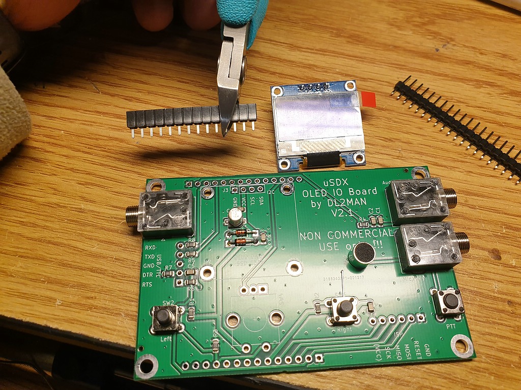
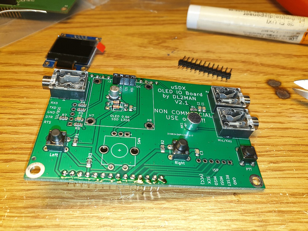
OLED IO-Board:
BOM_uSDX-Sandwich-IO-Board-OLED-checkedDOWNLOAD
You just need to source and place the THT Components.
Here´s the Schematic for the OLED IO-Board: Schematic_uSDX-IO-OLED_Rev2_1DOWNLOAD
Notes:
D1/D2 Standard 1N4148 Diodes
SW4 (rotary encoder) use EC11B13 (Unlike other rotary encoders, this one is known to work without trouble and comes at a reasonable price)
SW1-SW3 you can use for example these
MK1 (on-Board Mic) for example this one (watch for polarity !!!)
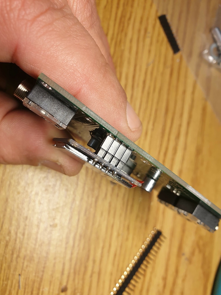
J4,J5,J6 use these
J1 and J2 are male jumper connectors, nothing special
J3 is Place Holder for OLED Display, like this one (if you buy another one, watch for the right order of the Pins)
J7 and J8 are Female Pin Sockets, with bent contacts for horizontal mount. Nothing special.


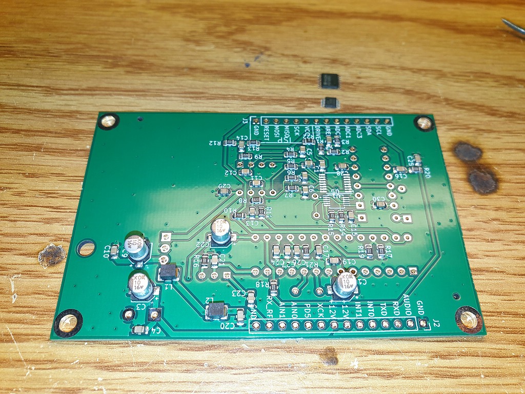
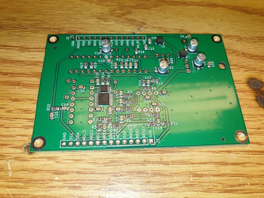
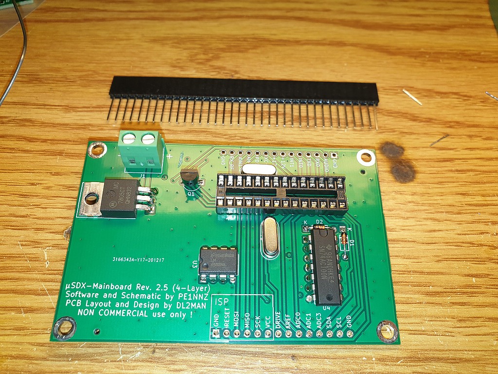
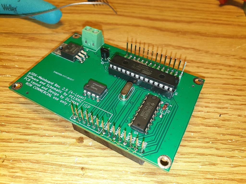
Mainboard
BOM_uSDX_Main_Rev2.5_4Layer-checkedDOWNLOAD
You just need to source and place the Si5351 and the FST3253 SMT IC´s and the THT Components. JLC-PCB do not have the IC´s in Stock and cannot place them for us.
Here´s the Schematc of the Mainboard:Schematic_uSDX_Main_Rev2.5_4LayerDOWNLOAD
Notes:
D1/D2 Standard 1N4148 Diodes
U4 is 74ACT00 in DIP-14 Package
U6 is ATMega 328 in DIP28 Package use Socket for that
U3 is LM4562 in DIP-8 Package
U5 is Si5351 in MSOP-10 Package
U1 is FST3253 in TSSOP-16 Package
U2 is 7805 in TO220 Package
Q1 BS170 in TO92 Package
J2 and J3 are cut from Male/Female Stacking Header Set
J1 is Terminal Block by Phoenix Contact, can be replaced by anything with5,08mm Pin-Spacing
Start with soldering U1 and U5 on the pre-populated board.
Here are some tips how to solder that without special tools:


8-Band RF Board
Comes naked, so it will be dealt with on the Main Page of this Board:
Software
In case, you still hear noise from OLED (change in Noisefloor when you unplug OLED)
Try another ATMega. Sounds stupid, but I had the case, that one ATMega would create audio humm (from OLED) the other not. Seems, like there is also Tolerances involved in their ADC Quality….